BRC: Grid Refinement – Quadrilaterals

The ability to refine quadrilaterals will allow me to process grids which discretize boundary layer regions with quadrilaterals and use triangles elsewhere.  This is an important step to being able to handle more realistic configurations which utilize quads/triangles in 2-D and prisms/tetrahedrons in 3-D.  Since Cobalt uses unstructured grids, I allow quadrilaterals to be refined as a mix of triangles and quadrilaterals.  This allows the refinement to remain localized.

My first test case contains only quadrilaterals in the grid.  It is the axi-symmetric bump of Bachalo and Johnson.  The slideshow below presents the grid in the top image and the corresponding solution, colored by pressure, in the bottom image.  A pressure difference of 5% was used as the refinement criteria.

The grid statistics are provided in the table below.  The grid score has not suffered as much as the pure triangle grids had.

OriginalRefinement 1Refinement 2Refinement 3Refinement 4
Number of Points22,32123,26824,49625,67228,087
Number of Faces44,32046,43949,31051,97257,517
Number of Cells22,00023,17224,81526,30129,431
Grid Score96.1996.1396.0395.9895.87

The second case is a NACA0012 which resolves the boundary layer with quads and uses triangles outside the BL. This case was run at a transonic condition to generate a shock along the airfoil for shock/BL interaction. The original and refined grids plus solution, colored by Mach number, are shown below. A pressure difference of 5% was also used to determine refinement for this case.

The table below shows the grid statistics for the original and refined NACA0012. The grid score has gone down by 1.21 over the four refinements.

OriginalRefinement 1Refinement 2Refinement 3Refinement 4
Number of Points22,04123,22725,48327,56631,349
Number of Faces56,16759,18364,97271,14382,492
Number of Cells34,12635,95639,48943,57751,143
Grid Score98.4898.3398.0597.7197.27

BRC: Grid Refinement – Triangles

It has been some time since I’ve had a project with exciting enough results, or just exciting enough, to feature in Bob’s Research Corner.  Recently, I started working on a topic that has interested me for many years.  We’ve all made grids were we’ve tried to capture certain flow features.  After obtaining a solution, we realized we needed more resolution in specific areas.  Unfortunately time constraints by the customer do not allow us to manually refine the grid to the level that is required.  This edition of Bob’s Research Corner will chronicle my attempts to develop a grid refinement utility.

I had originally looked into grid refinement back in 2011, but shelved the project since it was low priority.  At that time, I only looked a triangles and used Delaunay triangulation for refinement.  I had several concerns including high aspect ratio cells and different cells types (besides triangles and tetrahedrons).  Earlier this year, I focused some effort on overcoming those concerns and developed a method that might do so.

For me, grid refinement must meet three criteria:

  • Refine specified features
  • Make a valid grid
  • Minimize the degradation of grid quality

The first criteria is relatively straight forward, although some features might get over refined while trying to target specific areas.  The second criteria is probably the most difficult specifically for 3-D Boundary Layer grids and folded faces/negative volumes; the concern for 2-D is just making sure the new connectivity is correct.  Lastly, care must be taken to not offset the improved solution in certain areas by degrading the grid and the solution in other areas.  Initially, I will concentrate just on the first and second criterion. 

The first case I will use to test grid refinement is a supersonic ramp.  The inflow Mach Number is 1.9.  The solution has oblique shocks, a normal shock and an expansion fan.  This is an inviscid case, and the grid contains mostly nice, equilateral triangles.  A converged solution on the original grid was obtained; this solution was then used to refine the original grid.  A converged solution was obtained on the refined grid.  This process was repeated three more times.  The slideshow below shows the grid to the left and the pressure field on the right starting with the original grid and marching to the fourth refinement. You can click on each frame to zoom in on the image.  A pressure difference of 5% between cells was used as the refinement criteria.

The table below presents the statistics for the various grids.  The original grid has a very high score, almost perfect, at 99.72.  The fourth refinement grid results in a grid score of 96.53.  There has been some degradation of the grid which must be looked into further.

OriginalRefinement 1Refinement 2Refinement 3Refinement 4
Number of Points2,1272,9514,3416,89411,678
Number of Faces6,2228,68612,84720,49834,841
Number of Cells4,0965,7368,50713,60523,164
Grid Score99.7298.6597.6797.0396.53

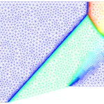
The second case is a 2-D cylinder, or circle, with a inviscid grid made up of only triangles. The incoming Mach Number is 5.0 and the Equilibrium Air model was used. The original grid was never intended for supersonic flow. It was a coarse grid for separated flow behind a cylinder. The slideshow below shows the grid on the left with the corresponding solution on the right. For this case, the flowfield is colored by density. Again, you can click on a frame to zoom in.

Grid statistics are presented in the table below. Like the Ramp, the original grid has a very high score of 99.62.  The fourth refinement grid results in a grid score of 95.93.

OriginalRefinement 1Refinement 2Refinement 3Refinement 4
Number of Points8,49911,48017,14527,41645,816
Number of Faces25,23034,12351,05481,813136,982
Number of Cells16,73122,64333,90954,39791,166
Grid Score99.6298.5897.4896.5995.93

Check back next month when I plan to have the refinement of quadrilaterals implemented.

Cobalt V8.0 Now Available

Cobalt V8.0 Released

Cobalt Solutions, LLC is pleased to announce the release of Cobalt V8.0. Several of the enhancements are listed below:

  • Addition of the Quadratic Constitutive Relation (QCR) for Spalart-Allmaras turbulence models.
  • Addition of the 2-D User Data boundary condition. This allows the user to specify variation of variables on a plane which is used to determine the boundary condition.
  • Modification to the for the User-Coded boundary condition to pass additional variables.
  • Modification to the Grid Deformer interface to load a grid deformer as a run-time library.
  • General improvements in the overall algorithm.

For more information and download instructions, please contact support.

BRC: Malleatus, part 3

The third milestone in making Malleatus production ready was to allow user control of the deformation of the boundary surfaces. I developed an interface such that the user can code how the boundaries move and pass/receive information to Malleatus. The exchange of information is shown below:

For this post, I revisited the F-16. I will show animations of twisting and bending of the the wing using the user-coded boundary movement library. Additionally, this case was run using small scale parallelization (up to 8 processors).Continue reading

BRC: Malleatus, part 2

The next milestone reached in the continued development of Malleatus was the determination of user input.  As always, we want to provide enough control to the user while not overwhelming them with unnecessary knobs.  I was able to minimize the user input to three values.  The first two control the amount of influence the movement of boundaries have on grid points;  the values must lie between 0.0 and 1.0. The final input controls the unfolding of folded faces algorithm.  Additionally, initial parallelization work has begun.

For this post, I revisited the Onera M6 wing.  I wanted to show solutions obtaining under bending and twisting using the new user input.  The conditions used for the simulation were: M= 0.8395, angle of attack = 3.06 degrees, Pressure = 98,920.475 Pa and T was 300 degrees K.Continue reading

Bob’s Research Corner: Malleatus, part 1

Last year the focus of Bob’s Research Corner was to report on the evaluation and testing of various grid deformation techniques.  This year, I’m going to chronicle the transformation of last year’s research code into a production utility.  I’ve decided to name this utility Malleatus.  Malleatus means “beaten or shaped by a hammer” which invokes images of using a hammer to bend and shape a grid.  But grid deformation also requires a delicate hand, and the name references malleus which is the hammer-shaped bone in the middle ear that transmits vibrations of the eardrum.Continue reading

Computational Aerodynamic Modeling for Flight Dynamics Simulation of Ram-Air Parachutes

Aerodynamic models were generated to simulate the flight dynamics of a parafoil wing with and without trailing-edge deflection. The airfoil was provided by the Natick Soldier Research, Development, and Engineering Center (NSRDEC) and was based on a modified Clark-Y with a flat lower surface used as the cut pattern for drop tested systems. The wing is characterized with an aspect ratio of two and zero anhedral angle. Several derivatives of this wing geometry were tested in the Subsonic Wind Tunnel (SWT) of United States Air Force Academy (USAFA).

These wings have either an open or closed inlet, a round or flat leading edge (for closed wings) and are with and without the trailing edge deflection. The flat leading edge wings consist of a straight line connecting the wing’s lower surface to the upper surface. The TE deflection is approximately 45 as measured from the flat lower surface. For convenience, these wings were named S R, B R, S F , B F , in which S and B denote straight and bent trailing edges; R and F indicate round and flat leading edges.

Continue reading

Journal Articles Added

The following journal articles have been added to our publications page:

Grid Quality and Resolution Effects for Aerodynamic Modeling of Ram-Air Parachutes
Ghoreyshi, Bergeron, Seidel, Lofthouse and Cummings, Journal of Aircraft, Vol 53, No 4, July-August 2016
Computational Aerodynamic Modeling for Flight Dynamics Simulation of Ram-Air Parachutes
Ghoreyshia, Bergeron, Jirásek, Seidel, Lofthouse and Cummings, Aerospace Science and Technology, Vol 54, Apr 2016
Vortical Flow Prediction of a Diamond Wing With Rounded Leading Edges
Ghoreyshi, Ryszka, Cummings and Lofthouse, Aerospace Science and Technology, Vol 57, Feb 2016

Canard-Wing Interference Effects on the Flight Characteristics of a Transonic Passenger Aircraft

Effects of canard wing interference on the flight characteristics of a civilian transonic cruiser are examined. The aircraft is an unconventional design concept with no historical data. The flight characteristics of the aircraft are predicted using aerodynamic models in the form of look-up tables, generated using high-fidelity computational fluid dynamics simulations and a potential ow solver. These tables contain longitudinal and lateral force and moment coefficients for different combinations of angle of attack, side-slip angle, and control surface deflections. Dynamic damping derivatives are calculated from time-accurate simulations of the aircraft models oscillating in pitch, roll, and yaw direction and using a linear regression estimation method. The static simulations are performed at a Mach number of 0.117, as reported in wind tunnel experiments, and for two different canard positions using an overset grid approach. The aerodynamic tables include canard deflections of [-30, -10, 0, 10] at angles of attack from -4 to 30 degrees. Lateral coefficients are simulated at sideslip angles of -6 and 6 degrees as well. The dynamic simulations are performed for aircraft oscillations about mean angles of attack between zero to ten degrees with a motion frequency of 1Hz and amplitude of 0.5 degrees. The predicted aerodynamic data are then compared with those measured in wind tunnel experiments and calculated from the potential ow solver. The results show that both static and dynamic predictions match reasonably well with experiments for the range of angles considered.Continue reading

Virtual Flight Testing of High Performance Fighter Aircraft Using High-Resolution CFD

This article discusses the current phase of a multi-year development effort to provide a computational method for determining static and dynamic stability and control characteristics of USAF high-performance fighter aircraft. The focus of this work is on the virtual flight test capability achieved by incorporating a pilot model, the F-16 flight control system (FLCS), and six degree-of-freedom (6-DoF) motion computation into the CFD maneuver simulation. Flight test maneuvers were performed in a virtual environment by using CFD to determine the forces and moments acting upon the aircraft and allowing the aircraft to respond as governed by the pilot model, FLCS, and 6-DoF. Virtual flight test simulations were accomplished with a full-scale F-16C aircraft using unstructured, viscous, overset grids and Cobalt with a MATLAB interface. Virtual flight test maneuver response is shown to compare well to validated, flight-test corrected data. This marriage of capabilities is rolled into a software suite known to the developers as COMSAC, which stands for COMputational Stability And Control.Continue reading