Aerodynamic models were generated to simulate the flight dynamics of a parafoil wing with and without trailing-edge deflection. The airfoil was provided by the Natick Soldier Research, Development, and Engineering Center (NSRDEC) and was based on a modified Clark-Y with a flat lower surface used as the cut pattern for drop tested systems. The wing is characterized with an aspect ratio of two and zero anhedral angle. Several derivatives of this wing geometry were tested in the Subsonic Wind Tunnel (SWT) of United States Air Force Academy (USAFA).
These wings have either an open or closed inlet, a round or flat leading edge (for closed wings) and are with and without the trailing edge deflection. The flat leading edge wings consist of a straight line connecting the wing’s lower surface to the upper surface. The TE deflection is approximately 45◦ as measured from the flat lower surface. For convenience, these wings were named S R, B R, S F , B F , in which S and B denote straight and bent trailing edges; R and F indicate round and flat leading edges.
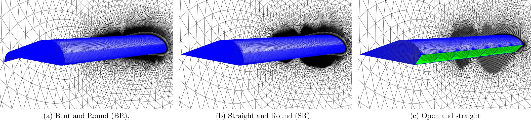
Coarse and fine RANS meshes were generated for these wings. These grids are unstructured with prismatic layers near the surfaces. Coarse grids were generated using CREATETM-MG Capstone code. Capston meshes are shown below. These meshes are symmetric (half-span) and have around 5.7 and 10 million cells for the closed and open wings, respectively. The right trailing edge is deflected in these meshes. All fine meshes correspond to the full wings and have a left-side trailing-edge deflection. Inviscid tetrahedral meshes were gen-erated by the ICEM-CFD code; these meshes were then used as a background mesh by the mesh generator of TRITET which builds prism layers using a frontal technique. TRITET rebuilds the viscous mesh while respecting the size of the original inviscid mesh from ICEM-CFD. The closed-wing meshes have around 30 million cells and the open-wing meshes contain about 45 million cells.
The simulation conditions are M = 0.25 and Re = 1.4 × 10⁶ corresponding to the wind tunnel experiments. The moment reference point and rotation points are at the wing quarter chord. Number of 2,000 and 8,000 CFD time steps were used for static simulation of closed and open wings, respectively. In all static simulations, second-order accuracy in time and 3 Newton sub-iterations were used. The last 1,000 time step values were then averaged to obtain aerodynamic coefficients of open wings. For dynamic simulations, five Newton sub-iterations with 2,000 time steps per cycle were used. The frequency in all motions is one Hz which corresponds to a reduced frequency of 0.01. This justifies the quasi-steady assumption required to estimate stability derivatives from these harmonic motions.
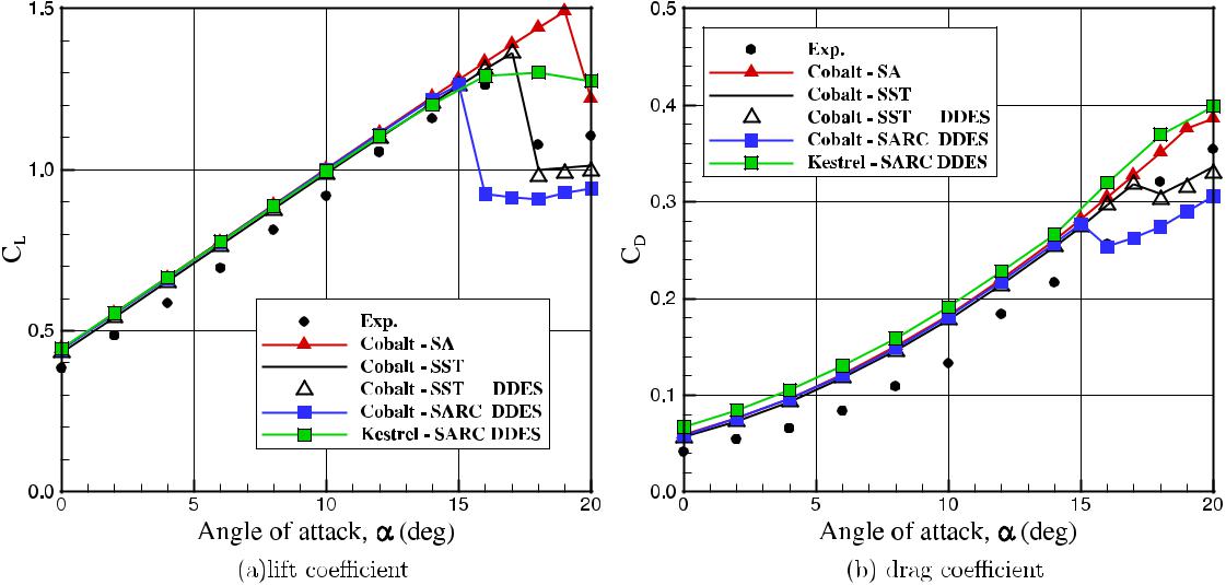
The figure below compares CFD data of the coarse grid of the BR wing using a symmetry plane with experimental data. Four different turbulence models and two different flow solvers were investigated. Cobalt was run with four turbulence models: Spalart–Allmaras (SA), Mentor’s SST and Delayed Detached Eddy Simulation with SST and SA with Rotation Correction (SARC). Kestrel predictions using the DDES-SARC turbulence model are also shown below. All solutions converged to steady-state values. The figure shows that none of the CFD data match exactly with experiment; CFD data overestimate the lift and drag coefficients. The figure shows that CFD data of both solvers and all turbulence models agree quite well with each other up to 15◦ angle of attack; the drag coefficient is slightly overestimated in Kestrel. However, CFD predictions are different above 15◦ . Cobalt with all used turbulence models predicts a sharp stall as the experiment does; Kestrel, on the other hand, predicts a smooth stall behavior. The stall angle and post-stall curves significantly change with the turbulence model selection. The SA model predicts the stall too late and the DDES-SARC predicts it too early compared with experiments. The SST turbulence model predicts the stall at the correct angle. Therefore, the SST model and Cobalt were used for all subsequent simulations.
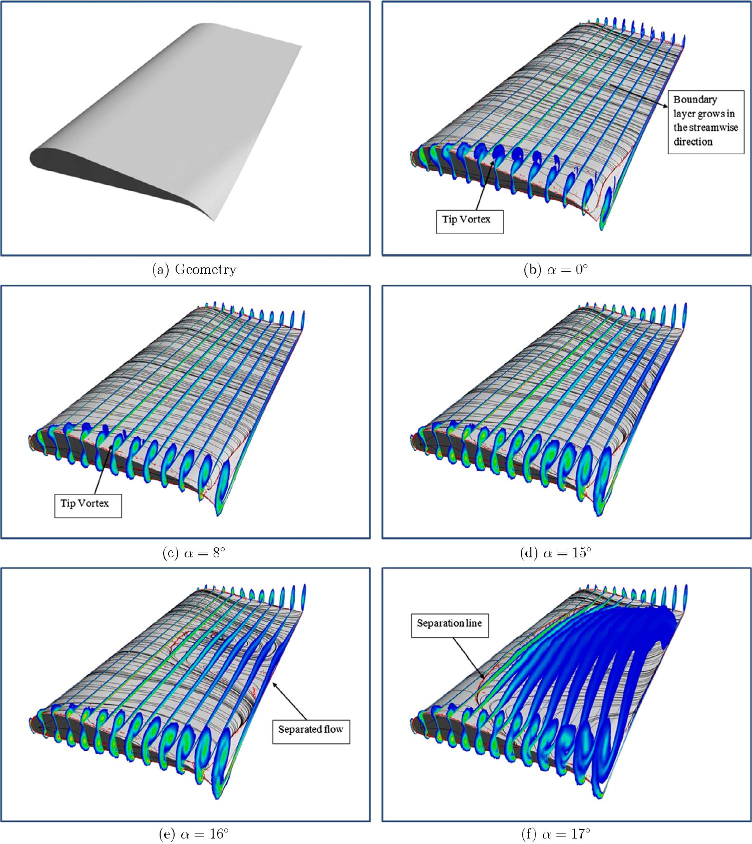
The flow solutions of the BR wing using SST turbulence model and the fine mesh are shown below for various angles of attack. Vortices are formed at the wing tips; these vortices are slightly different due to straight and bent sides. The figure hows that wingtip vortices grow in size as they move downstream and as the angle of attack increases. The image also shows that by increasing the angle of attack from 16◦ to 17◦ , a large separation region formed over the upper surface.
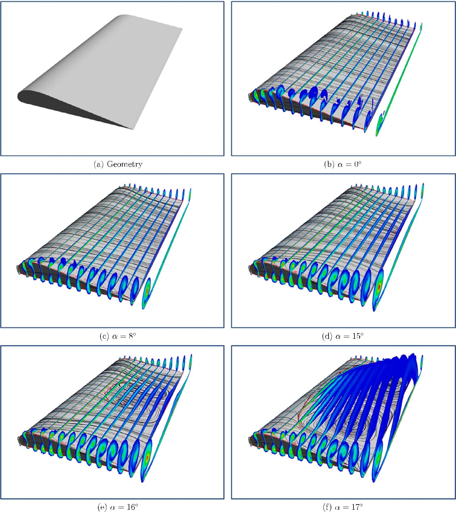
The flow solutions of the SR wing are shown in below for different angles of attack. The wingtip vortices can again be seen. Like the bent wing, the straight wing suddenly stalls at 17◦.
For further information, you can read the full paper, Computational Aerodynamic Modeling for Flight Dynamics Simulation of Ram-Air Parachutes, by Ghoreyshia, Bergeron, Jirásek, Seidel, Lofthouse and Cummings, Aerospace Science and Technology, Vol 54, Apr 2016